Learning hub-spoke with Packet Tracer and deploying it through Terraform on Azure
• 7 minute read
azure, packet-tracer, hub-spoke, terraform, networking
Table of contents
We'll understand how to build a hub-spoke network topology through practice. We won't cover many aspects of networking design though, such as proper subnetting, broadcast domain, dynamic routing, and others.
The hypothetical scenario
Let's say we have the following scenario:
- Your company will have three sites.
- Each site may have more than 60.000 hosts.
Download the laboratory file and open it on the Packet Tracer. You'll see the following:
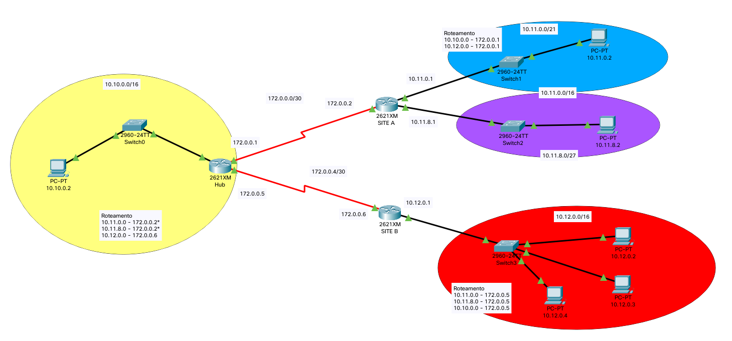
Each router has a name:
- Site A: It represents a spoke.
- Site B: It represents a spoke.
- Hub: The hub virtual network is the central point of connectivity. If we had more spokes, the topology would look like a star. Let's imagine it being our main site.
We'll complete the configuration through static routing.
Configuring each router in the Packet Tracer
This is the configuration for the hub router:
Router> enable
Router# config t
Router(config)# no ip domain-lookup
Router(config)# hostname hub
hub(config)# int f0/0
hub(config-if)# ip address 10.10.0.1 255.255.0.0
hub(config-if)# no shut
hub(config-if)# int s0/2
hub(config-if)# ip address 172.0.0.1 255.255.255.252
hub(config-if)# clock rate 64000
hub(config-if)# no shut
hub(config-if)# int s0/3
hub(config-if)# ip address 172.0.0.5 255.255.255.252
hub(config-if)# clock rate 64000
hub(config-if)# no shut
hub(config-if)# exit
hub(config)# ip route 10.11.0.0 255.255.0.0 172.0.0.2
hub(config)# ip route 10.12.0.0 255.255.0.0 172.0.0.6
hub(config)# exit
hub# write
The line where we set the serial interface with the clock rate is only required to make the configuration work. Usually, the clock rate is defined by the modem to which the serial interface connects. This is the configuration for the site-a router:
Router> enable
Router# config t
Router(config)# no ip domain-lookup
Router(config)# hostname site-a
site-a(config)# int f0/1
site-a(config-if)# ip address 10.11.0.1 255.255.248.0
site-a(config-if)# no shut
site-a(config-if)# int f1/0
site-a(config-if)# ip address 10.11.8.1 255.255.248.0
site-a(config-if)# no shut
site-a(config-if)# int s0/2
site-a(config-if)# ip address 172.0.0.2 255.255.255.252
site-a(config-if)# no shut
site-a(config-if)# exit
site-a(config)# ip route 10.10.0.0 255.255.0.0 172.0.0.1
site-a(config)# ip route 10.12.0.0 255.255.0.0 172.0.0.1
site-a(config)# exit
site-a# write
This is the configuration for the site-b router:
Router> enable
Router# config t
Router(config)# no ip domain-lookup
Router(config)# hostname site-b
site-b(config)# int f0/1
site-b(config-if)# ip address 10.12.0.1 255.255.0.0
site-b(config-if)# no shut
site-b(config-if)# int s0/2
site-b(config-if)# ip address 172.0.0.6 255.255.255.252
site-b(config-if)# no shut
site-b(config-if)# exit
site-b(config)# ip route 10.11.0.0 255.255.248.0 172.0.0.5
site-b(config)# ip route 10.11.8.0 255.255.248.0 172.0.0.5
site-b(config)# ip route 10.10.0.0 255.255.0.0 172.0.0.5
site-b(config)# exit
site-b# write
We could summarize the routes 10.11.0.0/21 and 10.11.8.0/21 to 10.11.0.0/16. You can try it if you want. When we finish the configuration, we can ping each host using a protocol data unit (PDU). It's interesting to notice that the first ICMP package does not work because the ARP protocol needs to find the MAC address 👀. Another interesting exploration to do is to execute show ip route and show ip interface brief on each router.
The same scenario on Azure using Terraform
Download the project and follow the prerequisites in the README file. Now run the container:
docker compose run --rm docker-client-tf-did bashExecute terraform init followed by terraform apply and await its conclusion.
Notice: We are not using Azure Virtual Network Manager, though it's highly recommended. Know how to create hub-spoke topology through it.
Details about the translation
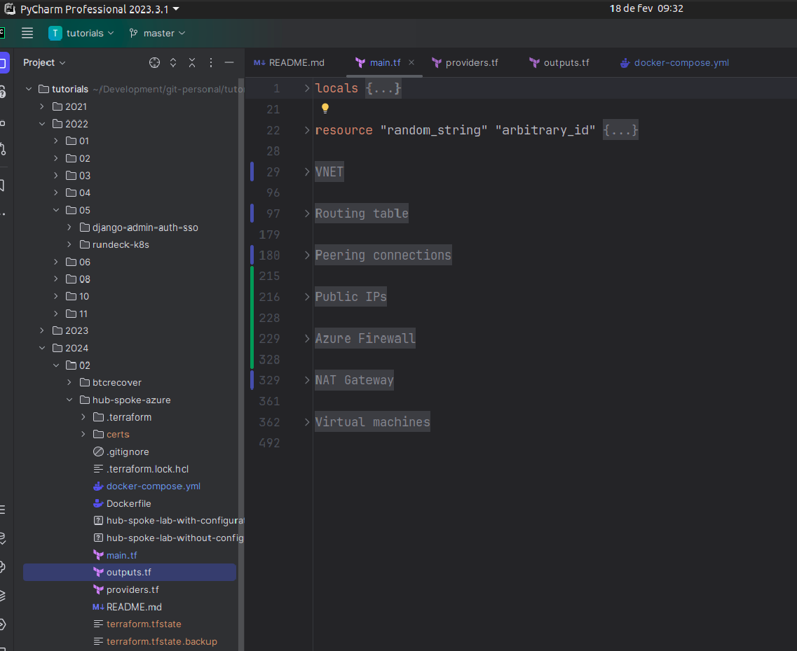
You'll see the following regions in the main.tf file:
In terms of VNet addresses, we have the following:
- Spoke site A: 10.11.0.0/16.
- Spoke site B: 10.12.0.0/16.
- Hub: 10.10.0.0/16.
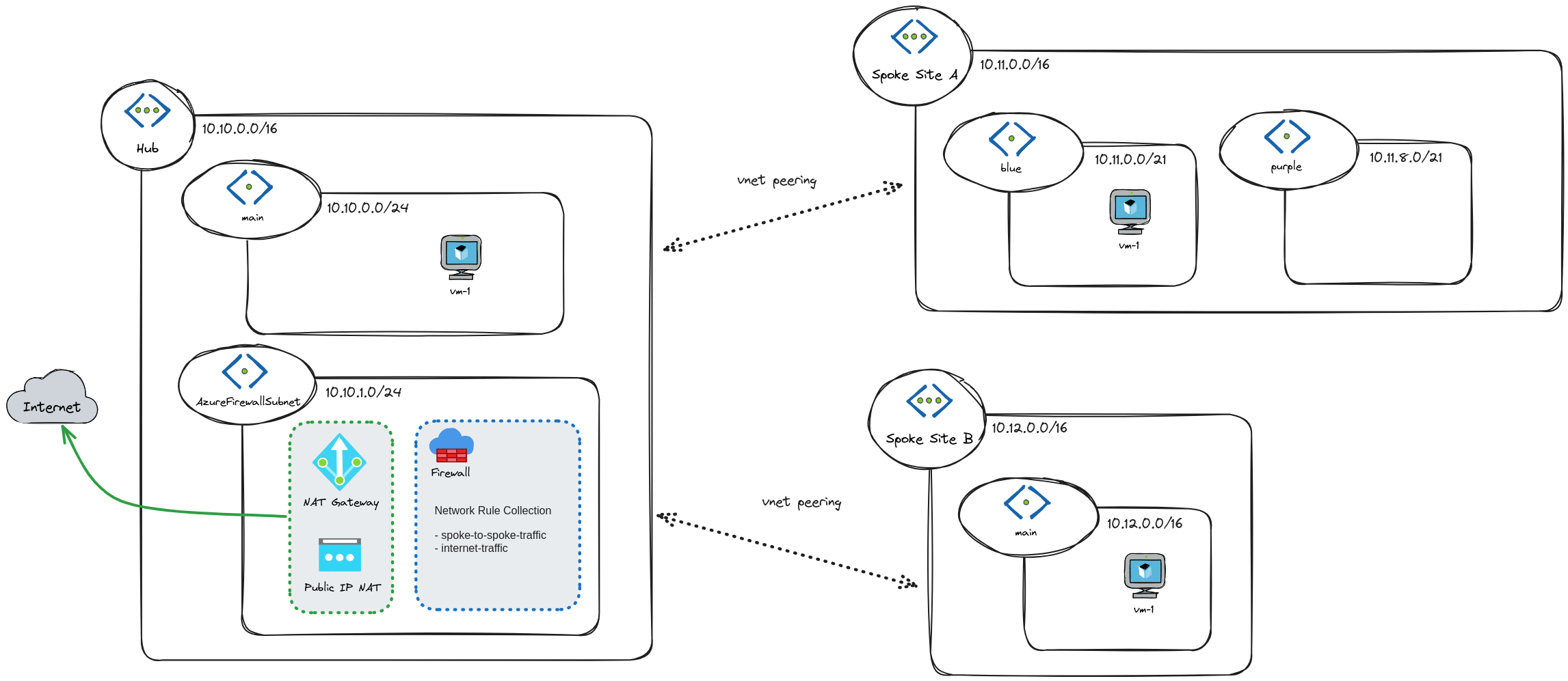
Spoke site A is the only one that has two subnets. The other two only have one. If we look at how each network communicates with each other in the Packet Tracer, the router is responsible for it, given how the routing is configured. On the other hand, Azure does not work this way; it does not work by configuring the routing table solely. Using the hub network for transit (read more about service chaining), we have three solutions:
- Use a Virtual Network Appliance (VNA) and configure it to route traffic to and from spoke A and V.
- Create a Virtual Network Gateway of type VPN for gateway transit.
- Use Azure Firewall to route traffic between VNets. It also secures and inspects network traffic.
The translation uses the option 3. Azure Firewall requires a particular subnet, so we have an additional one for the hub network. Look at the article Spoke-to-spoke Networking for further details regarding other possible solutions.
In terms of outbound connectivity, we are going to use NAT Gateway. It can provide internet access from the hub virtual network for all spoke virtual networks peered.
Testing connectivity using Ping
Pick up a virtual machine from spoke site A and connect to it using the serial console:
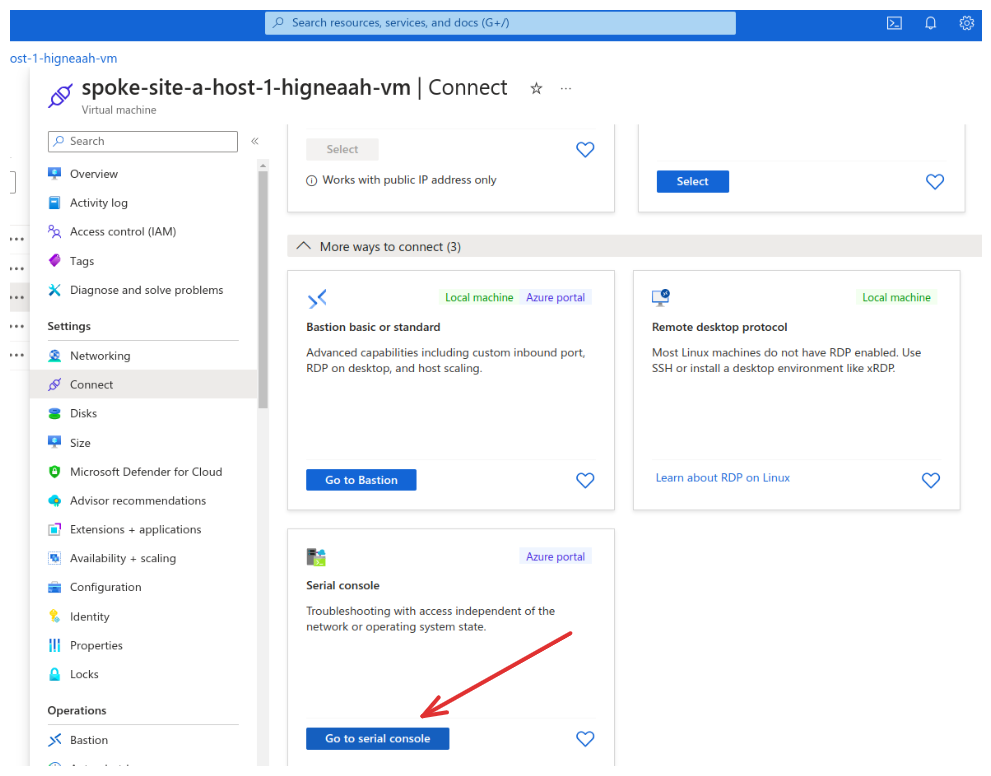
Use the user spoke-site-a-host-1 and the password returned from the terraform output vm_password command. Ping the IP 10.12.0.4 and check it out! 😉
Testing connectivity using Network Watcher
You can use this approach to test connectivity in many ways. For example, what is the next hop from a virtual machine in spoke site A that targets the IP of a virtual machine in spoke site B?
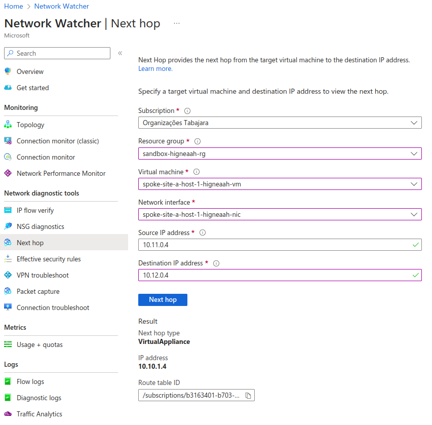
With Network Watcher, we don't need to access the machine to test connectivity.
Conclusion
Suppose you have to learn how to design and implement networking topologies, though you only know the very basics. In that case, it's highly recommended to do it first on the Packet Tracer to comprehend theories, then go to a cloud service such as Azure. Learning by practice is fantastic because you consolidate everything through mistakes we usually face in production environments.
See everything we did here on GitHub.
Posted listening to Pride And Joy, Stevie Ray Vaughan & Double Trouble 🎶.